Difference between revisions of "BBC:Microbit / Calliope"
| (3 intermediate revisions by the same user not shown) | |||
| Line 1: | Line 1: | ||
| − | The BBC micro:bit is a Microcontroller that is designed to be easily programmable by young students. The Calliope is a very similar device, designed to be compatible to the Microbit. Hence, we discuss both on the same page with a focus on the Microbit. You should be able to load the same programs onto the Calliope (for differences, see section [[#Calliope]]. | + | The BBC micro:bit is a Microcontroller that is designed to be easily programmable by young students. The Calliope is a very similar device, designed to be compatible to the Microbit. Hence, we discuss both on the same page with a focus on the Microbit. You should be able to load the same programs onto the Calliope (for differences, see section [[#Calliope]]). |
Which experiment configuration you can use with the Microbit depends on the program loaded onto the microcontroller. You will need to enable the Bluetooth functions with such a program first, so there are no experiments included with phyphox, but example combination of Microbit code and phyphox configurations can be found below. | Which experiment configuration you can use with the Microbit depends on the program loaded onto the microcontroller. You will need to enable the Bluetooth functions with such a program first, so there are no experiments included with phyphox, but example combination of Microbit code and phyphox configurations can be found below. | ||
| Line 157: | Line 157: | ||
== Calliope == | == Calliope == | ||
| − | To connect to the | + | To connect to the Calliope, it is best to connect the Calliope with the official Calliope Application to the device running phyphox. If the Calliope is not connecting, try reflashing the start program with USB [https://calliope.cc/programmieren/mobil/hilfe] and connect the Calliope again with the official app. If it is not shown in phyphox, try to hit the reset button once. |
| + | |||
| + | In the phyphox experiments for the micro_Bit above, the "bluetooth name" tag has to be changed to "Calliope mini". | ||
| + | |||
| + | Here are two simple files to read the magnetometer and the acceleration sensor: [[Media:Calliope_Magnetometer.phyphox]] and [[Media:Calliope_Acceleration.phyphox]] | ||
Latest revision as of 17:45, 21 December 2022
The BBC micro:bit is a Microcontroller that is designed to be easily programmable by young students. The Calliope is a very similar device, designed to be compatible to the Microbit. Hence, we discuss both on the same page with a focus on the Microbit. You should be able to load the same programs onto the Calliope (for differences, see section #Calliope).
Which experiment configuration you can use with the Microbit depends on the program loaded onto the microcontroller. You will need to enable the Bluetooth functions with such a program first, so there are no experiments included with phyphox, but example combination of Microbit code and phyphox configurations can be found below.
Important: Unlike most other Bluetooth Low Energy devices, the microbit needs to be paired with the phone to be used. You should use the Microbit app to do that (or the Bluetooth settings on Android - was not able to do this without the Microbit app on iOS).
Contents
- 1 Read magnetometer
- 2 Read acceleration sensor
- 3 Read IO Pins
- 4 Write number to LED service
- 5 Move point on LED service
- 6 Measuring the voltage at a potentiometer and calculate its current resistance value
- 7 Measuring the voltage drop and the illumination value of a photoresistor
- 8 Measuring the capacitor voltage while (dis-)charging a capacitor
- 9 Calliope
Read magnetometer
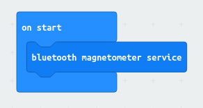
To make the magnetometer available via Bluetooth, you just need to write a minimal program for the Microbit that starts the magnetometer Bluetooth Service once:
Reading the magnetometer in phyphox can simply be done by reading the characteristic E95DFB11-251D-470A-A062-FA1922DFA9A8 as defined in the documentation. This returns three unsigned 16bit little endian integers, so we only need to pick them at their respective offsets:
        <bluetooth name="BBC micro:bit">
            <output char="E95DFB11-251D-470A-A062-FA1922DFA9A8" offset="0" conversion="int16LittleEndian">Bx</output>
            <output char="E95DFB11-251D-470A-A062-FA1922DFA9A8" offset="2" conversion="int16LittleEndian">By</output>
            <output char="E95DFB11-251D-470A-A062-FA1922DFA9A8" offset="4" conversion="int16LittleEndian">Bz</output>
            <output char="E95DFB11-251D-470A-A062-FA1922DFA9A8" extra="time">t</output>
        </bluetooth>
Unfortunately, the unit is not entirely clear and on the device we used to test, each value overflowed upon rotation. The result is that we get numbers in the range of -32000 to +32000 which overflow at several points during rotation from one end to the other. It is not clear to us whether this is an issue for the specific micro:bit we used for testing, but this behavior can clearly be seen in the raw data when reading the magnetometer service with other apps as well.
You can use the following ready-to-use configuration in phyphox to try it yourself. Don't forget to load the correct code onto your micro:bit first and to freshly pair it with your phone:
Media:BBC Microbit Magnetometer.phyphox
Read acceleration sensor
The acceleration sensor is read similarly to the magnetometer, the only difference is the characteristic, which is "E95DCA4B-251D-470A-A062-FA1922DFA9A8". One has to change the axis labels, but that is all. For the the acceleration sensor of the Calliope, here is an experiment file: Media:Calliope_Acceleration.phyphox.
Read IO Pins
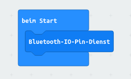
To make the IO pins available via Bluetooth, you just need to write a minimal program for the Microbit that starts the IO Bluetooth Service once:
That's it. Upload it to your Microbit and it is ready to be used (don't forget to pair it).
Now, at the phyphox end, you need to figure out, on which characteristic the data can be received and how it is formatted. According to the Microbit documentation, this is E95D8D00-251D-470A-A062-FA1922DFA9A8, but the response will be a series of byte pairs and each pair gives the pin number and its value. In principle, we could even match and parse these in phyphox, but for this simple example, we can make our life a bit easier by only using a single pin. If there is only one pin that is read, the io data will be a single pair of bytes. The first will always be the pin number and the second will be the value. Therefore, if set up correctly, we only need to read the second byte of E95D8D00-251D-470A-A062-FA1922DFA9A8:
<output char="E95D8D00-251D-470A-A062-FA1922DFA9A8" offset="1" conversion="singleByte">v0</output>
Now, how do we tell the Microbit that we only want a single pin? Well, there are the characteristic E95DB9FE-251D-470A-A062-FA1922DFA9A8, which is a bit mask (a series of 1s and 0s, where each digit represents an option), that defines which pin is an input and which is an output. We only set one of those to "1" and the others to "0", which means that only one pin is an input. Also, there is characteristic E95D5899-251D-470A-A062-FA1922DFA9A8 with a similar bit mask, with which we can tell the Microbit that we want to do an analog read. So, we do the following config:
<config char="E95D5899-251D-470A-A062-FA1922DFA9A8" conversion="hexadecimal">01000000</config>
<config char="E95DB9FE-251D-470A-A062-FA1922DFA9A8" conversion="hexadecimal">01000000</config>
(A little detail as this might be confusing: The Microbit looks at the 20 least significant bits, so we want to set the "x" in the pattern xxxxxxxxxxxxxxxxxxxx000000000000 (20 "x" and 12 "0" to get a total of 32 bits). phyphox requires an input in hexadecimal, so groups of 8 bits are expressed as a byte in hexadecimal: xxxxxxxx xxxxxxxx xxxx0000 00000000. Setting the first bit leads to the hexadecimal number 01 00 00 00. Why not 80 00 00 00? Because we want to set the least significant bit, not the first one in the first one written in our notation.)
Finally, we also want to have a time axis, so we tell phyphox to also save the time when a new value arrives:
<output char="E95D8D00-251D-470A-A062-FA1922DFA9A8" extra="time">t</output>
So, in total we have
<bluetooth name="BBC micro:bit">
    <config char="E95D5899-251D-470A-A062-FA1922DFA9A8" conversion="hexadecimal">01000000</config>
    <config char="E95DB9FE-251D-470A-A062-FA1922DFA9A8" conversion="hexadecimal">01000000</config>
    <output char="E95D8D00-251D-470A-A062-FA1922DFA9A8" offset="1" conversion="singleByte">v0</output>
    <output char="E95D8D00-251D-470A-A062-FA1922DFA9A8" extra="time">t</output>
</bluetooth>
The following experiment configuration does all the above and also adds a little calibration. This calibration assumes that the range is 3V and that we have a single byte (a number from 0 to 255), so it is just 3V/255. Note, that the Microbit is designed to measure voltages. This is only an estimate and you will encounter effects that would be unusual for a real voltmeter, but that are typical for analog inputs of a microprocessor (like floating voltages and a battery dependent logic level as reference).
So, just try this configuration in phyphox:
Media:BBC Microbit Voltage.phyphox
Write number to LED service
This example works in the other direction. We will use the accelerometer of the phone to detect a shake. For each shake, we count upwards and write the numer of shakes to the LEDs of the Microbit.
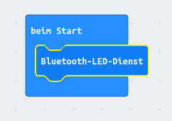
On the Microbit, you only have to enable the LED service:
The phyphox experiment can now simply write numbers to the characteristic E95D93EE-251D-470A-A062-FA1922DFA9A8, so any number we want to show on the Microbit, can be written as follows:
<bluetooth name="BBC micro:bit">
    <input char="E95D93EE-251D-470A-A062-FA1922DFA9A8" conversion="singleByte">char</input>
</bluetooth>
The rest of the experiment simply reads the accelerometer, checks if it is above a threshold and than adds one to the counter. You can try it below:
Media:BBC Microbit Counter.phyphox
Move point on LED service
This is just another example. As above, it only requires the LED service:
The experiment configuration is rather complex because it needs to compose the bits that have to be written to the LED service. It is probably only relevant if you want to do something similar and you should really know how the phyphox experiment configurations work:
Media:BBC Microbit Matrix.phyphox
Measuring the voltage at a potentiometer and calculate its current resistance value
Note: Each of the following experiment configurations uses the 3V- and GND-PIN of the BBC micro:bit as supply voltage and the voltage is measured using the I/O-PIN 0. The measured voltage data is transferred from the BBC micro:bit to the smartphone via BLE with a resolution of 3,3V/255.
Media:Aufbau_Potentiometer.png
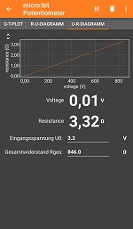
This experiment configuration measures the variable voltage while changing the resistance value of a potentiometer. The configuration calculates the current resistance value and plots the calculated Resistance R with the measured Voltage V on the x- and y-axis and vice versa.
Experiment configuration (QR-Code):
Measuring the voltage drop and the illumination value of a photoresistor
Media:Aufbau_Fotowiderstand.jpg
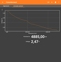
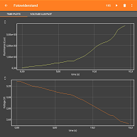
This experiment configuration measures the voltage drop of a photoresistor as a function of its illumination level or both as functions of time (synchronous).
The voltage is measured with the micro:bit, the illumination in Lux is measured with the intern light sensor of the smartphone. Just place the smartphone light sensor next to the photoresistance and use a variable light source with illumination uniformity. Start the exeriment with a low illumination level, then increase the illumination of the light source.
Experiment configuration (QR-Code):
Measuring the capacitor voltage while (dis-)charging a capacitor
Media:Kondensatorschaltung.png
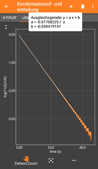
This experiment configuration measures the voltage drop of a capacitor in series with a resistance as a function of time.
The data is analysed by logarithmic functions, so that a linear regression in the phyphox app is possible for both charging and discharging. In each case the negative, inverse slope value represents the time constant τ.
Experiment configuration (QR-Code):
Calliope
To connect to the Calliope, it is best to connect the Calliope with the official Calliope Application to the device running phyphox. If the Calliope is not connecting, try reflashing the start program with USB [1] and connect the Calliope again with the official app. If it is not shown in phyphox, try to hit the reset button once.
In the phyphox experiments for the micro_Bit above, the "bluetooth name" tag has to be changed to "Calliope mini".
Here are two simple files to read the magnetometer and the acceleration sensor: Media:Calliope_Magnetometer.phyphox and Media:Calliope_Acceleration.phyphox
